O-Rings for Dynamic Sealing Applications
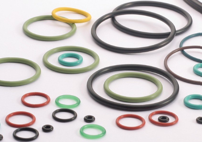
O-rings are most commonly used in static sealing applications – think flanges, end caps, and housings where there is no relative motion between mating parts. Thanks to their simple geometry, easy installation, low cost, and reliable sealing performance, they have become the most ubiquitous sealing element in industry.
However, because of their unique elastic deformation characteristics, self‑sealing effect, and good adaptability to gland geometries, O‑rings can also be used in dynamic sealing applications under certain conditions – including reciprocating piston rods and cylinders, rotating shafts, and oscillating mechanisms.
When you use an O‑ring in a dynamic application, you need to pay much closer attention to a range of critical parameters compared to static seals. These include:
Compression set
Stretch amount
Groove fill percentage
Friction coefficient and wear characteristics under dynamic conditions
Frictional heat generation and its effect on the material’s temperature resistance and compression set performance
Only by carefully balancing these parameters in your design can you fully realise the potential of O‑rings in dynamic sealing – and avoid premature failure caused by excessive wear, spiral twist, or heat‑induced ageing.
The following sections will walk you through the basic classifications of dynamic sealing, design guidelines for reciprocating, rotary and oscillating applications, material selection, failure modes, and real‑world application examples.
Table of content
- Static vs. Dynamic Seals: Understanding the Difference
- Dynamic O-Ring Seal Design: Critical Requirements
- Material Selection for Dynamic Seals
- Linear Sealing Applications
- OTE Rubber: Your Partner for Dynamic Sealing Solutions
1.Static vs. Dynamic Seals: Understanding the Difference
Static Seal
A static seal creates a barrier between two surfaces that experience no relative motion during normal operation. Once compressed between the mating surfaces, the seal remains fixed. Common static applications include flanged connections in piping systems, pressure vessel closures, pump casings, valve bonnets, and access covers on equipment.
Dynamic Seals
A dynamic seal must maintain sealing integrity while accommodating continuous or intermittent relative motion between components.
This motion can be reciprocating (as in hydraulic cylinders, pneumatic actuators, piston rods), rotational (as in pump shafts), or oscillating (where the shaft moves in an arc)
2. Dynamic O-Ring Seal Design: Critical Requirements
Dynamic O-ring sealing applications are more complex than static applications due to the presence of motion and friction. Several critical design factors must be addressed to ensure reliable performance.
2.1 Compression Control
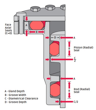
Compression is the percentage reduction of the O-ring cross-section when installed. In dynamic applications, the compression margin must be minimized to reduce sliding resistance, wear, and heat generation. To create seal squeeze, the gland must be less than the cross-section depth.
As a general rule, static seal cross-sections are compressed from 15% to 30%, whereas dynamic seals are compressed from 10% to only 20%. For reciprocating dynamic applications such as hydraulic cylinder rod and piston seals, recommended dynamic squeeze ranges are 8–20%.
The appropriate compression directly affects sealing effectiveness, friction, wear, and the risk of spiral failure. Excessive compression increases friction and heat — which is particularly detrimental for dynamic seals — while insufficient compression reduces contact sealing force and increases leakage risk.
2.2 Surface Finish Requirements
Surface finish is a critical factor in dynamic sealing. The material of the gland must not abrade the O-ring during motion, and surface finishes must be compatible to prevent tears and failures.
For maximum seal life, the surface finish of metal parts in contact with an O-ring should not exceed:
Static parts: 0.8 µm (32 µin) CLA or Ra
Moving parts: 0.4 µm (16 µin) for moving parts
Typically, the ideal hardware surface finish for dynamic seals is between 10 and 20 micro-inches (0.25 µm to 0.5 µm) Ra. A finish finer than 0.15 µm (6 µin) should be avoided in dynamic applications as a lubricating film may not be retained. Anything below 5 micro-inches will cause adequate surface lubrication to be rubbed away by the end of the stroke.
A surface finish that is too abrasive will wear the O-ring surface, while a surface that is too smooth will not allow the O-ring to be properly lubricated by a fluid film.
2.3 Groove Fill and Volume
Groove fill describes how much of the groove volume the O-ring occupies. For dynamic applications, the groove volume should allow a fill of approximately 60–70%. If the groove is overfilled, there is no room for thermal or chemical expansion, causing overstress or failure. If underfilled, the O-ring may not generate sufficient sealing force. Further, the maximum O-ring volume should not exceed the minimum volume of the gland.
2.4 Lubrication
Before O-ring installation, always lightly coat the O-ring with a lubricant that is compatible with both the O-ring material and the system chemicals.
OTE rubber could offer different lubrication on the O-RING surface, such as PTFE, MuS2.So that less friction force can be achieved for dynamic sealing.
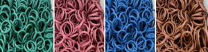
PTFE could be a idea option when combined with rubber material in order to improve wear resistance.
In the meantime, OTE rubber also developed self-lubricated rubber material. It could offer lower friction force during the lift time.
3. Material Selection for Dynamic Seals
Dynamic seal design prioritizes wear resistance, low friction coefficients, controlled compression set, and dimensional stability during motion.
3.1 Material Hardness Considerations
Normal compounds (60–70A) offer better conformability and low initial leak rates but have higher compression set and wear. Harder compounds (80–95A) resist extrusion and high-pressure blowout but increase friction.
According to research on the effect of NBR hardness on hydraulic O-ring rod seals:
Low hardness seals are prone to stress concentration due to extrusion under high-pressure conditions and are more prone to leaking
High hardness seals better prevent leakage by reducing fluid film thickness, but cause larger frictional power loss and increase the probability of wear failure
The choice of lower hardness is recommended to reduce friction, provided that leakage requirements are met
The optimized selection of rubber hardness depends on application conditions:
Normal hardness is suitable for high-speed or low-leakage-requirement applications, while higher hardness is preferable for high-pressure working conditions.
3.2 Fluid Compatibility
When selecting a rubber material for a dynamic sealing application, you must consider two fundamental factors simultaneously: compatibility with the sealed medium and the operating temperature range. These two parameters are closely interconnected and directly determine the service life and reliability of the O-ring.
First, the elastomer must be chemically compatible with the fluid or gas it will seal. Incompatible materials can swell, soften, shrink, or crack, leading to rapid failure. For example, standard NBR (nitrile rubber) works well with mineral oils and fuels but fails in brake fluids or ozone-rich environments. FKM (fluoroelastomer) offers excellent resistance to high-temperature oils, fuels, and many aggressive chemicals, but it is not compatible with skydrol (phosphate ester hydraulic fluids) or low-molecular-weight organic acids.
Second, you must evaluate the continuous and intermittent temperature extremes that the seal will encounter in dynamic service. Frictional heat generated by reciprocating or rotary motion often raises local temperatures significantly above the bulk system temperature. A material that performs well at 100°C in a static test may degrade rapidly at 130°C under dynamic conditions due to thermo‑oxidative ageing, leading to increased hardness, compression set, and eventual leakage.
The key is to balance both requirements – a material that is perfectly compatible with the medium but lacks sufficient thermal stability will harden and crack; conversely, a high-temperature material that swells excessively in the medium will lose its mechanical properties and sealing force. For demanding dynamic applications such as hydraulic cylinders operating at 150°C with petroleum‑based fluids, a high‑grade FKM or HNBR (hydrogenated nitrile) is often the right choice. For even higher temperatures (200°C+) or aggressive chemical environments, FFKM (perfluoroelastomer) may be necessary.

Always validate your material selection by consulting compatibility charts, performing immersion tests per ASTM D471, and considering the maximum local temperature – not just the bulk fluid temperature. When in doubt, OTE’s engineering team can assist you in selecting the optimal compound for your specific medium, temperature range, and dynamic duty cycle.
4. Common Failure Modes in Dynamic O-Ring Seals
Understanding how dynamic O-rings fail is essential for preventing premature replacement and system downtime.
4.1 Extrusion and Nibbling
Extrusion and nibbling of the O-ring is a primary cause of seal failure in dynamic applications such as hydraulic rod and piston seals. Extrusion occurs when high pressure forces the O-ring material into the clearance gap between mating hardware components. Once extruded, material may shear off during reciprocating or vibratory motion, a phenomenon referred to as nibbling. Damage typically appears on the low-pressure side of the O-ring, characterized by jagged, frayed, or “chewed” edges.
In an O-ring that has failed due to nibbling, it may appear as if many small pieces have been removed from the low-pressure side. In some forms of extrusion, more than 50% of the O-ring may be destroyed before catastrophic leakage is observed. Extrusion can also occur in static applications subject to high-pressure pulsing, which causes the clearance gap of mating flanges to open and close, trapping the O-ring between the mating surfaces.
Primary causes of extrusion: Excessive clearances, high pressure beyond system design, O-ring material too soft, degradation by system fluid (swelling/softening/shrinking/cracking), irregular clearance gaps due to eccentricity, improper machining of the O-ring gland (sharp edges), and improper size O-ring installed (too large) causing excessive filling of the groove.
Recommended solutions: Decrease clearance by reducing machining tolerances; increase the durometer (hardness) of the O-ring material; use backup rings; break sharp edges of the gland to a minimum radius of 0.002 inches (0.05 mm); ensure proper size O‑rings are installed; increase rigidity of metal components; and verify O-ring material compatibility with system fluid.
4.2 Spiral Failure (Twisting)
Spiral failure is a dynamic failure mode typically seen in reciprocating seals, manifesting as a tight spiral or corkscrew-shaped tear across the O-ring’s cross-section. Unlike extrusion, the O-ring may continue to seal until the damage progresses to complete rupture.
Spiral failure occurs when uneven friction during reciprocating motion causes the O-ring to twist. A properly functioning O-ring slides during reciprocating motion, aided by pressure-induced friction. Spiral failure occurs when portions of the O-ring twist because of uneven frictional conditions. Pressure then pushes the twisted seal into the clearance gap, and the progressive twisting eventually leads to rupture.
This failure mode is more likely when the seal becomes “hung-up” at one point on its diameter against the cylinder wall and simultaneously slides and rolls. Common contributing factors include high surface roughness due to missing or incorrect lubricant, excessive friction, inadequate lubrication, misaligned hardware, and improper groove design.
4.3 Abrasion and Wear
Abrasion results from the O-ring sliding against the counterface, often accelerated by:
Particulate contamination in the fluid
Excessive surface roughness of mating hardware
Insufficient lubrication
High-frequency cycling
4.4 Thermal Degradation
Frictional heat generation from dynamic motion can lead to thermal degradation of the elastomer, causing hardening, cracking, or softening. This is particularly relevant in high-speed rotary and long-stroke reciprocating applications where heat cannot be adequately dissipated.
At high temperatures, the elastomer hardens, leading to increased friction and accelerated wear; simultaneously, its diminished resilience means the seal can no longer maintain adequate contact pressure against the mating surface, resulting in premature leakage. For these reasons, accurately evaluating the maximum operating temperature the seal will experience is critical, and a temperature safety margin should be included.
5. Linear and Rotary Applications
Linear Seals
Reciprocating seals are used where a piston or rod moves linearly within a cylinder. This is the most common dynamic application for O-rings. Key considerations include:
Stroke length: Thicker cross-section O-rings are demanded by longer stroke applications
Passing over ports: Passing O-rings over ports is not recommended — nibbling and premature wear will result
Pressure cycling: Pressure shocks can exceed extrusion resistance; backup rings or higher-durometer materials may be required
Spiral failure risk: Uneven friction conditions along the stroke can cause twisting, leading to spiral failure
Rotary Seals
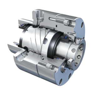
Rotary seals are used on rotating shafts, with the turning shaft protruding through the inside diameter of the O-ring. While O-rings can be used for rotary applications, special considerations apply:
Low speeds only: O-rings are generally suitable only for low peripheral speeds; for higher speeds, specialized rotary seals are recommended
Lower squeeze: Minimal squeeze (closer to 0.15–0.25 mm interference) reduces friction and heat generation
Higher hardness: Harder compounds (80–90 Shore A) typically perform better
Internal lubrication: Self-lubricating compounds are strongly preferred
Temperature management: Operating temperatures should remain as close to room temperature as possible; higher speeds increase frictional heating
For recommendations on rotary applications, consulting the seal manufacturer’s technical team is advised to confirm suitability for the specific speed, pressure, and temperature conditions.
OBT Rubber: Your Partner for Dynamic Sealing Solutions
At OBT Rubber, we understand the unique challenges of dynamic sealing applications. Our engineering team brings extensive expertise in designing O-rings that withstand the demanding conditions of reciprocating and rotary motion.
Our Capabilities
Wide compound to meet specific wear resistance, friction, and temperature requirements. Rubber material include: NBR, FKM, HNBR, EPDM, silicone, and specialty elastomers.
Precision molding ensuring consistent cross-sectional geometry and tight tolerances
Gland design optimization support, including surface finish recommendations, squeeze calculations, and extrusion gap analysis
Rapid prototyping to validate seal designs before full production
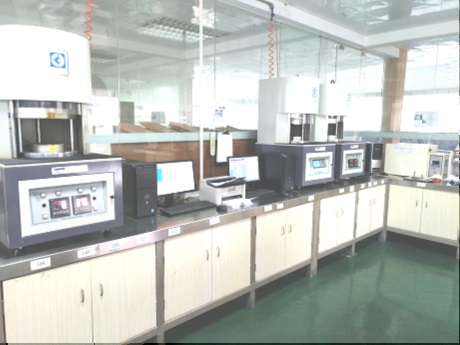
Rubber material testing including compression set (ASTM D395), fluid compatibility, and dimensional verification
Thanks to contact us to discuss your requirements regarding O-RINGs. We are ready to assist you with fast, reliable support.